
After soldering module CC Debugger (last module) i need to program internal flash with TI firmware. I havn't any TI development tools and decide use Arduino for program. Repository contains PDE file for Arduino and C# project for front-end on PC.
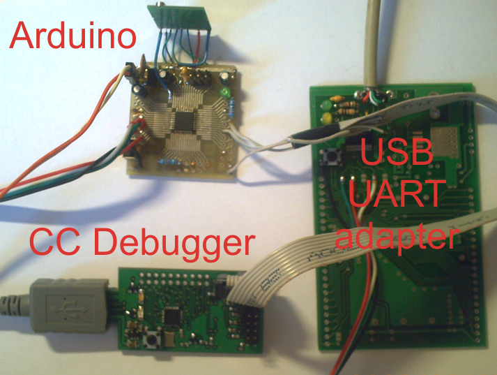
First step - connect 3 wire from arduino to CC debugger:
PD5 > CC DC line
PD6 > CC DD line
PD7 > CC RESET line
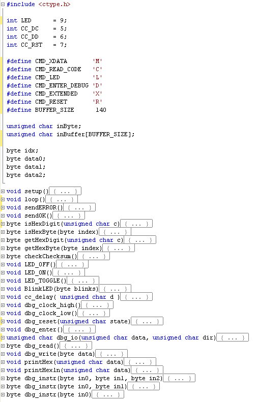
and write sketch to access CC lines from host computer via serial port.
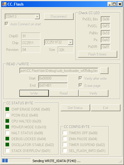
Second program on C# to work with CC memory via Arduino and write original TI bootloader for CC debugger (converted to binary format)
Third step write original TI CC debugger firmwire to CC debugger with SmartFlash software
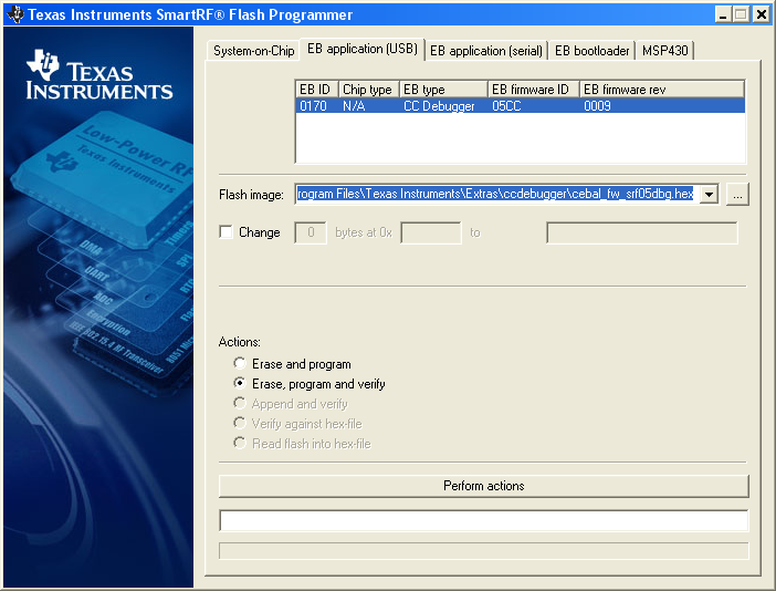
after all done CC debugger work and i can programm all other modules.

31 comment(s) so far
Hi, is it possible to simplify this setup with a teensy2 board?
I guess I can omit the usb-uart-adapter when I use that teensy2 board.
My problem is atm: "GET_CHIP_ID error: Bad value ff
(i get bad value 00, if its not connected to the cc-debugger)
Do I need to power the cc-debugger by USB? Do I need to connect the GND of my teensy board to the GND of the cc-debugger?
I'm having issues getting you CC.flash.exe working. I hit the connect button and I see signals on the DD,DC and RST lines but I don't get any errors from the program it just stops connecting. Any tips?
Hello, how can make the arduino as the cc debugger ?
In theory yes - but i never make this. Easy make CC debugger on CC2500.
Hi, is it possible to make CC debugger on CC1111 or CC2541? If yes, what needs to be changed?
Need connect and check
Hi,
I configured your C# code to programming CC2540 only few line was enough. But groupAllControls wasnt enable after the detected the IC. Then i add the enable command into the chipModel_SelectedIndexChanged function to enable it.
Not it is enabling the screen after detected the IC and verify the device codes.Getting device status as "CPU Halted andOscillator Stable"
But Write, Read and Verify functions not working. And Read command stopping when reached 64kb file. Returning 0xFF and 0x00. Write is stopping after first page uploaded because of cpu_status not returning a value after 5 repeat.
Do you have any idea about that? groupAllControls problem is know code problem by you? or am i missing something at start?
Thanks
Melih
I never use with CC2540. Published as is and use for your risk.
Melih
Were you ever able to program the CC2540 using this method? Can you give me your what you changed in the code and I will try myself and see if I can't figure out how to do it.
StormBard
Does the arduino board used matter? I've got a pro-mini that I was thinking about using.
I successfully connect arduino with cc2541 chip using your code, it can communicate together ( I capture on serial communication, on read chipid it reply READ : 4111245), but actually the chip is not supported, could you please update c# code so, it can support cc2541 chip? (actually I have same problem with melih).
Hi All,
I was trying to connect arduino based debugger, but when I press connect button I get the same error as "Joe" reported
"oe
Saturday, February 09 2013
I'm having issues getting you CC.flash.exe working. I hit the connect button and I see signals on the DD,DC and RST lines but I don't get any errors from the program it just stops connecting. Any tips?"
Is there a known issue?
I'm running on a windows 7 machine
Thank you very much for your work on this! I have the standard CC2511 USB Dongle (seen here: http://www.ti.com/graphics/tool/CC2511EMK.jpg) and an Arduino Uno, and I'm not the best at interpreting diagrams. It looks like I need to connect pins 3, 4, and 7 from the DEBUG 10-pin cluster on the CC2500 to pins 5, 6, and 7 on the Arduino - is this correct?
Also getting the same errors as Jay and Shatruddha - Arduino sketch has been uploaded, launch the program & it fails to connect.
Connection correct (only add ground) and not not use long wires. I use 8MHz Arduino but Uno use 16MHz - so may be change cc_delay() to increase timing.
Ok, thanks for the clarification. I've increased the timings (tried doubling the timing numbers & halfing them to troubleshoot); I have everything connected as described, and the app stlil won't connect. Anything else you'd recommend for troubleshooting?
Check signal DC, DD, RST on CC2511. Toggle on arduino and see on CC2511 pins. Also see CC timimg diagram and change to delay micro/milliseconds to tune accuracy.
HI i want develop BLE Module Using CC2540/CC2541
Can I use This Code to burn TI bootloader pls Reply Urgent
This pcb == TI CC debugger. Must works. Arduino simulation for C2 protocol need to check.
How do you convert the cebal*.hex to binary format?
Find hex2bin on Keil.com site or in google
Hi, wanna use the Arduino Mega 2650 as CC.debugger and to programm HM-11 (CC2541) with HID bridge example from
( github.com/.../cc2540-hidKbdM ).
I got everything connected and followed the steps:
1. Upload CC_Flash.pde sketch to Arduino (sucess Arduino was programmed)
2. Connect
Target Arduino Mega
DC (P2.1) - pin 5
DD (P2.2) - pin 6
RST - pin 7
GND - GND
3. Start program CC.Flash.exe (need .NET 2.0)
... so I can start the CC.Flash.exe , it displays the right COM port but I can not connect, everytime I press connect, the programm tries to but nothing happens.
Any advice?
Thanks,
Andi
Hi,
Thanks for the solution, I'm stuck with a bricked CC Debugger due to some unknown event during upgrade. The CC.Flash connects the CC 2511 but all the options (except Disconnect) are greyed-out. I'm using Windows 7/64.
Thanks,
Dan
Hi,
Could you please share Arduino's code?
Thanks!
github.com/.../CC_Flash.pde
Hello! Can you help me? O'm tying to flash cc1111 chip by you method. But can't :(
Commands to chip looks good - like regular SPI, but responses from chip looks bad. drive.google.com/.../view Why this can be so?
Thx.
Hello.
I have a problem. The program cc.flash connects to the cc2511 chip but I can not upload anything to it. All buttons in the application are inactive.
In the link you have a photo.
www.serwis.tv/.../cc_flash.jpg
Hello.
I have a problem. The program cc.flash connects to the cc2511 chip but I can not upload anything to it. All buttons in the application are inactive.
In the link you have a photo.
www.serwis.tv/.../cc_flash.jpg
Check arduino pde part.
Connect via any serial terminal at 115200 and send command directly.
I check only with 8MHz Arduino.
Communication between CC @ Arduino:
TX:
D45
XW168R2D3
XW134R1CB
XW134R1CB
RX:
OK
:685253
OK
:888749545682506851
READ:910496
OK
:888749515282496766
READ:B6B7
OK
:888749515282496766
READ:B6B7
OK
Only suggest run under Visual Studio and debug.
Now i havn't arduino and cc debugger.
Can't help you with protocol debug.